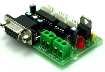
This is A quick Method To solve An issue with Rs485 Cable
작성자 정보
- Franklyn 작성
- 작성일
본문
Selects parity. ---- Enters a command. Selects a baud rate. Page 37 Setting example of parameters (2-wire RS485 communication) Parameters relating to the master side (example) Master (transmission of output frequency (%) (100% at FH)) Selection of communication protocol (Toshiba inverter protocol) Communication baud rate (ex. The maximum sustainable baud rate on the secondary serial port is 4800 baud. Typical line voltage levels from the line drivers are a minimum of ±1.5 V to a maximum of about ±6 V. Receiver input sensitivity is ±200 mV. 6.1. Proportional control of speed Proportional control of frequency can be performed in two ways: control by selecting frequency points and control by adjusting the ratio to the maximum frequency. 9600 baud, even parity, 8-bit length, 1 stop bit --- Specifies the communication number for monitoring the output frequency. 9600 baud, even parity, 8-bit length, 1 stop bit --- Reads in data to be sent to the inverter. S command is used and the slave inverters do not return the data. 8.3. Utilizing panel (LEDs and keys) by communication The VF-AS1 can display data that is not related to the inverters through an external controller or other means. MODBUS-RTU decides the data that is first received subsequently as the first byte of a frame after a blank time for 3.5 bytes at the on-going communication speed.
Use this function for the following case: When the data response from the inverter is too quick after the PC had sent the data to the inverter, PC process cannot get ready to receive the data, or when the USB/RS485, RS485/RS232C con- verter is used, changeover of sending and receiving data takes much time in the converter process. This menu includes a function to adjust the Modbus ID number and a screen cleaning function. The easiest and the best way to connect the devices in a MODBUS RTU - RS485 communication is using DAISY CHAIN method. The RS485 is required to enable the Modbus communications to function on Model 77x-type products. Page 60 Block Communication Function for LED Display To display LED data for ASCII display that is synchronized to each digit, set data for each digit and validate this set data by display selection by communication (Communication Number FA65). Synchronization can also be achieved by batch writing LED data parameters after changing the fol- lowing block communication mode parameters and by sending data by block communication.
Page 49 Terminal board output data (FA50) The output terminal board on each inverter can be directly controlled with the computer. If bit 0 through bit 6 of terminal board output data (FA50) are set with the computer, data specified (0 or 1) can be sent to any output ter- minal. The large standard cable offering at Remee, along with expert capabilities to modify any standard cable and manufacture complex and custom-made cables, are proof of our significant industry stature. Available in many standards, offering a range of flexibility and data transmission speeds for your application. Failure to stay within this range will result in, at best, signal corruption, and, at worst, damage to connected devices. For communication purposes, see the parameter list on inverter's instruction manual regarding the communication number, adjustment range and so forth. See "8.1 Command by communication" for the method to enable them. When enabling the communication command by Communication Command 1, commands by communication can be given the priority irrespective of the setting of the command mode selection parameter (). 8. Commands and monitoring from the computer Across the network, rs485 cable instructions (commands and frequency) can be sent to each inverter and the operating status of each inverter can be monitored.
8.1. Communication commands (commands from the computer) Communication command (Communication number: FA00, FA04) Commands can be executed on inverter frequencies and operation stop through communication. Command processing will be executed only broadcast communication "0" and with those inverters that match set inverter numbers. 8.3.2. Key utilization by communication The VF-AS1 can use the panel keys on the inverters through external communication. Appendix 2 Response time The communication response time can be calculated from data communication time and inverter processing time. 5.1. MODBUS-RTU transmission format MODBUS-RTU sends and receives binary data without a frame-synchronizing start code and de- fines the blank time to recognize the start of a frame. Rather, the UART deduces the correct time to sample the incoming signal based on the start and stop bits in the signal itself. 3) Common interface chips like the 8250/16450/16550 UART used for asynchronous communication and flow control between devices. High (mark) parity means that the parity bit is always logic 1 at the UART, and low (space) parity means that the parity bit is always logic 0 at the UART. Each RS232 driver uses inverting logic and implements a single-ended bipolar output voltage (that is, one signal that swings above and below ground).

관련자료
-
이전
-
다음

